I have been running MySensors and OpenHAB for a while now. The system is set up on a Raspberry Pi 3, running OpenHABian. I have built and deployed some basic MySensors nodes in my apartment, measuring things like room temperature and humidity. I have some “smart” IoT devices to control with OpenHAB.
My home automation project begin as a prototype, but by now it’s become clear that the system is useful and I want to expand it. This means that the “I’ll just throw a RPi onto a rack shelf” approach needs upgrading. I have a proper rack, why can’t the RPi be properly racked?
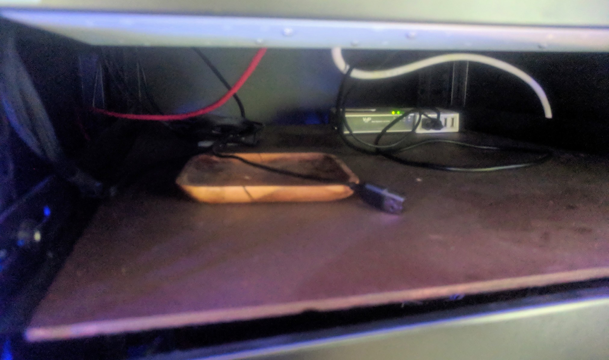
I had an empty Soekris 1u net6501 enclosure, which fit the bill.
Business Plan
Drill new holes into the Soekris enclosure, mount the Pi-s into it; rackmount the entire thing. No more free-floating Pi-s on a shelf. #labporn
Bonus points: replace the stock NRF24L01+ radio with the more powerful long-range version (external antenna); and support MySensors ERROR, RX and TX LED-s.
The Build
I started by measuring and drawing the layout in Inkscape. By printing the panel design on paper, I could get hole guidelines for drilling.
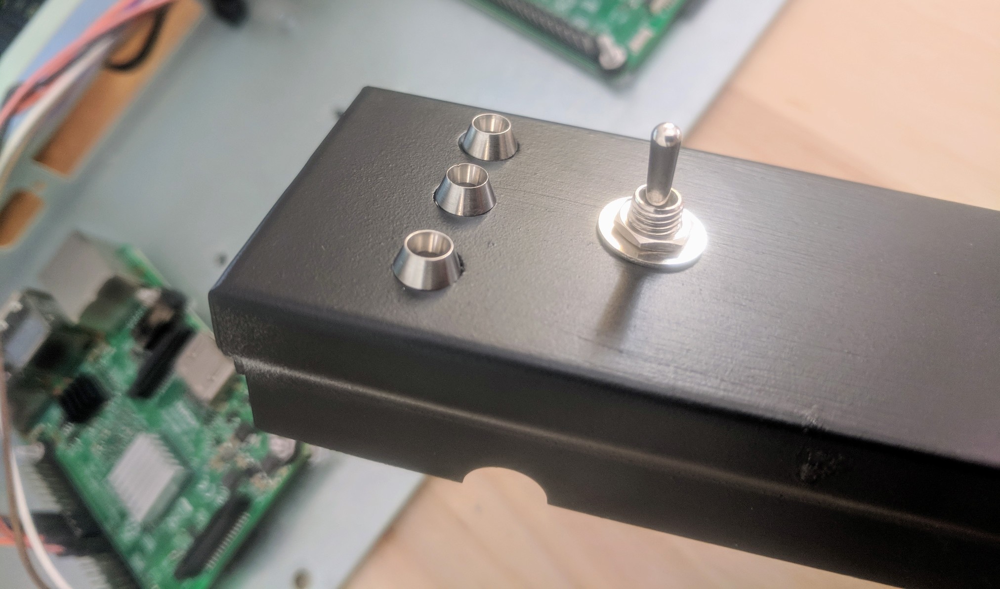
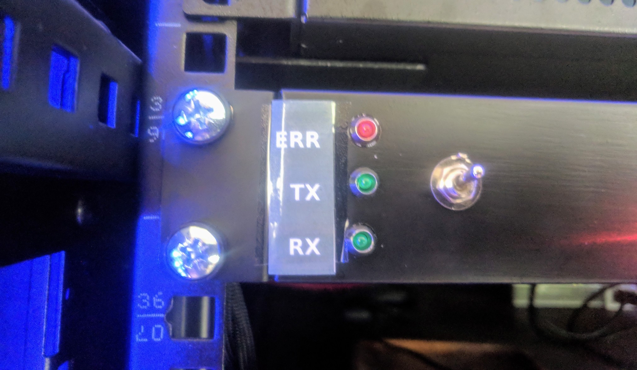
I planned to mount 3 LED-s to the 1u front panel for MySensors, + a toggle switch for stopping / starting home automation services on the Pi. The toggle switch would allow Eveli to turn off all home automation services, should something error out and become UnbearablyAnnoying.
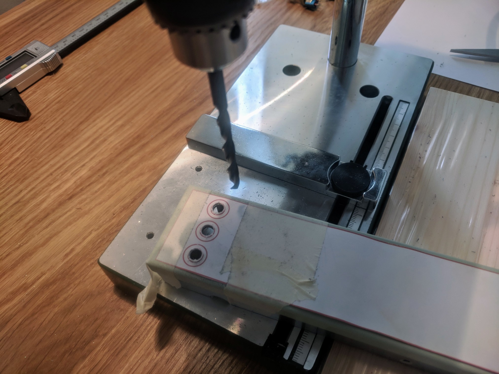
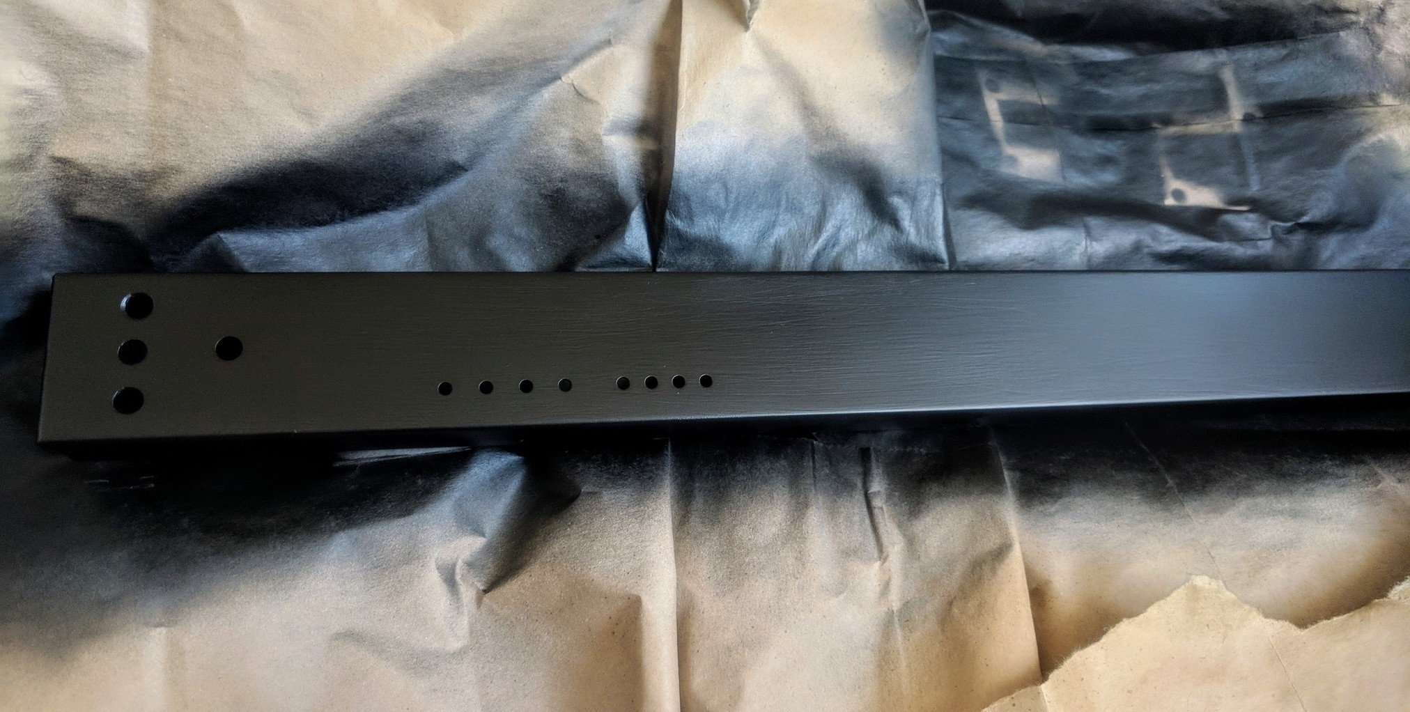
Light sandpaper took care of removing the original Soekris paint and text. Three layers of spray-paint later I had a nice-looking black front panel.
I used through-hole 3mm LED sockets and a small toggle switch.
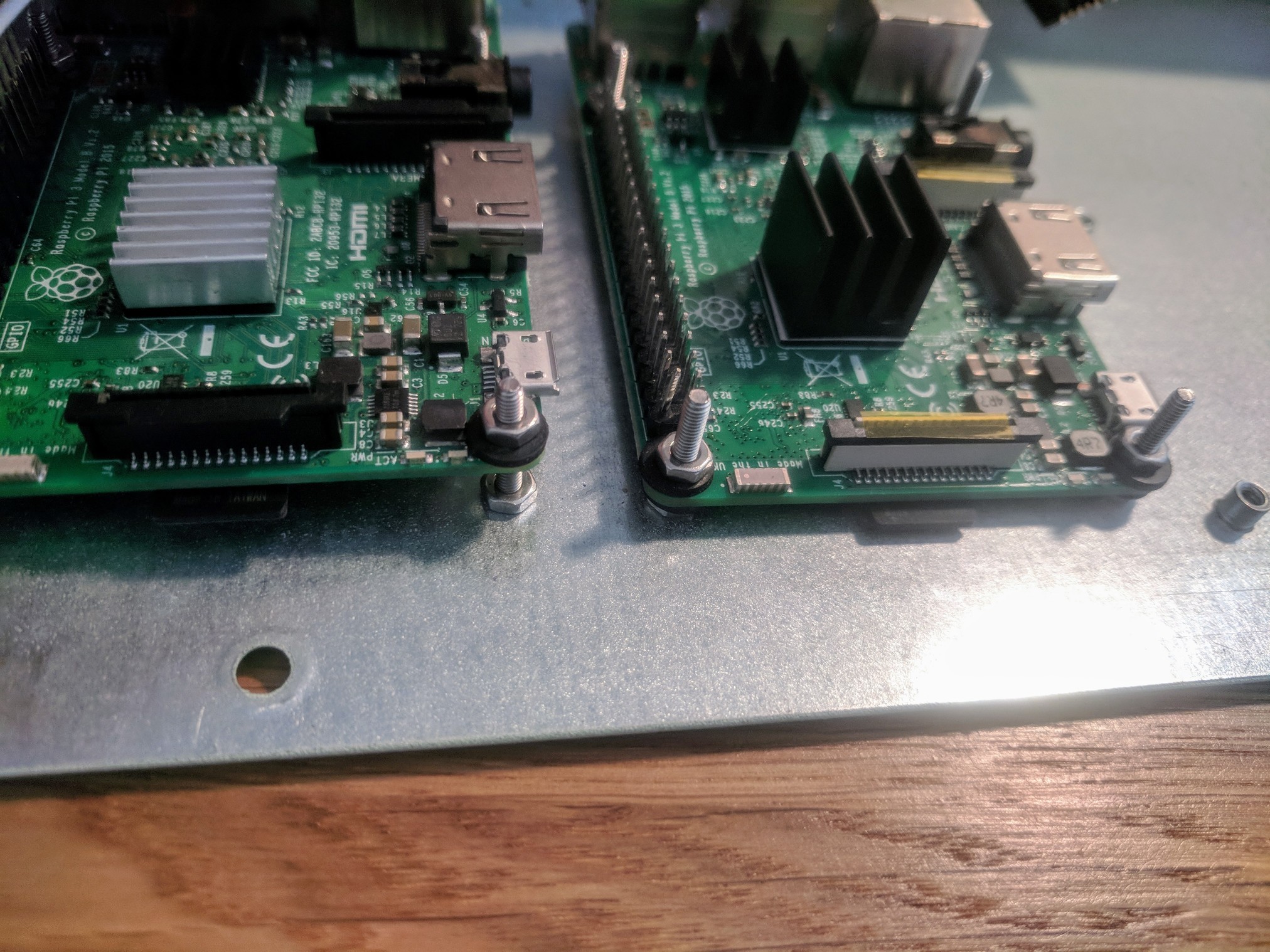
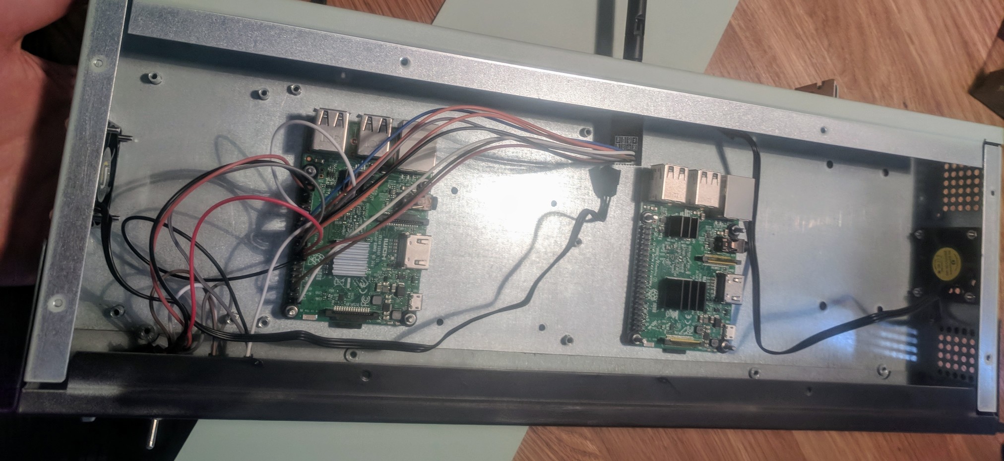
I drilled eight 2.5mm holes for mounting two Raspberry Pi-s (the 2nd Pi just rents the space in the enclosure) and Eveli proceeded to screw them in place.

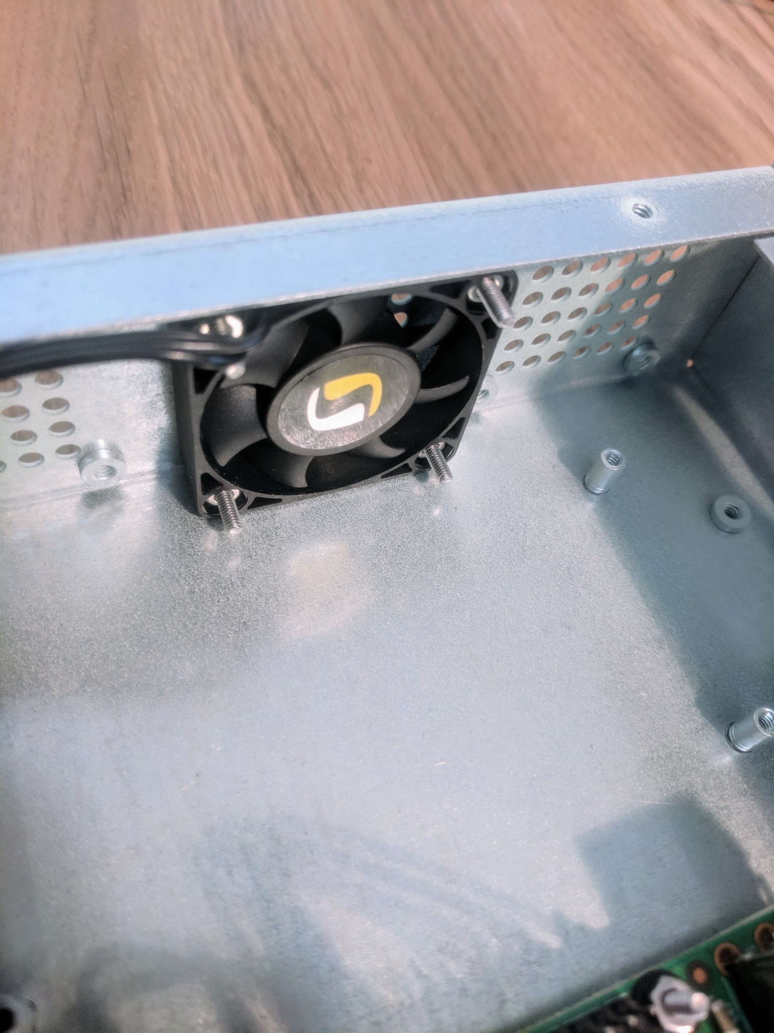
I also added two 40mm fans to the sides of the enclosure for keeping things cool. The fans presented a problem, as they run on standard 12V, however I have no such power source available from the Pi-s. This problem will be solved in the future, somehow.
The back of the enclosure (the addon card slot) also got it’s hole for the antenna mount of the radio.

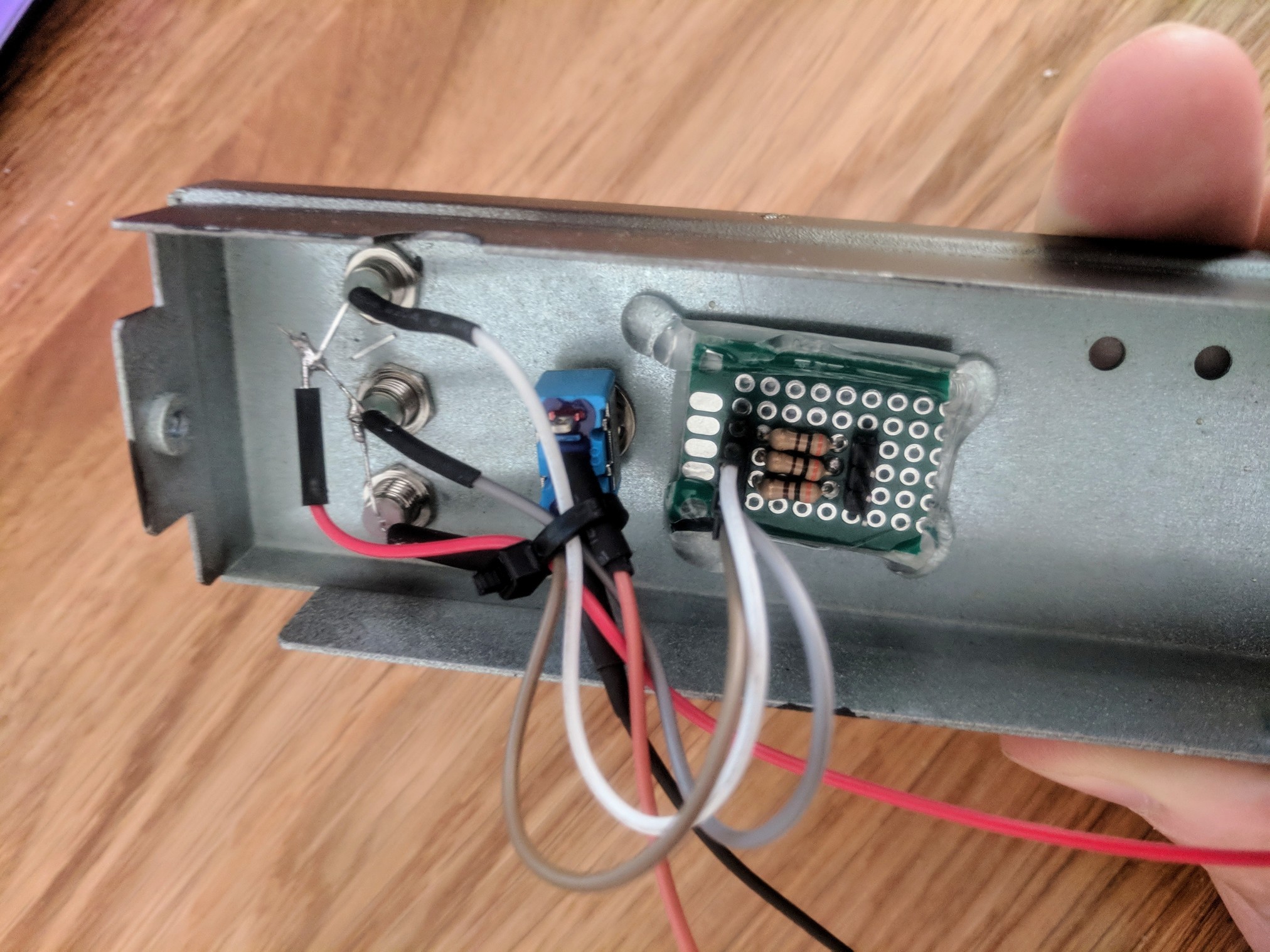
Electronics on the front panel needed connecting to the PI. I created a very small PCB module for adding the required 300Ω resistors to the LED-s and connected them to RPi GPIO pins.
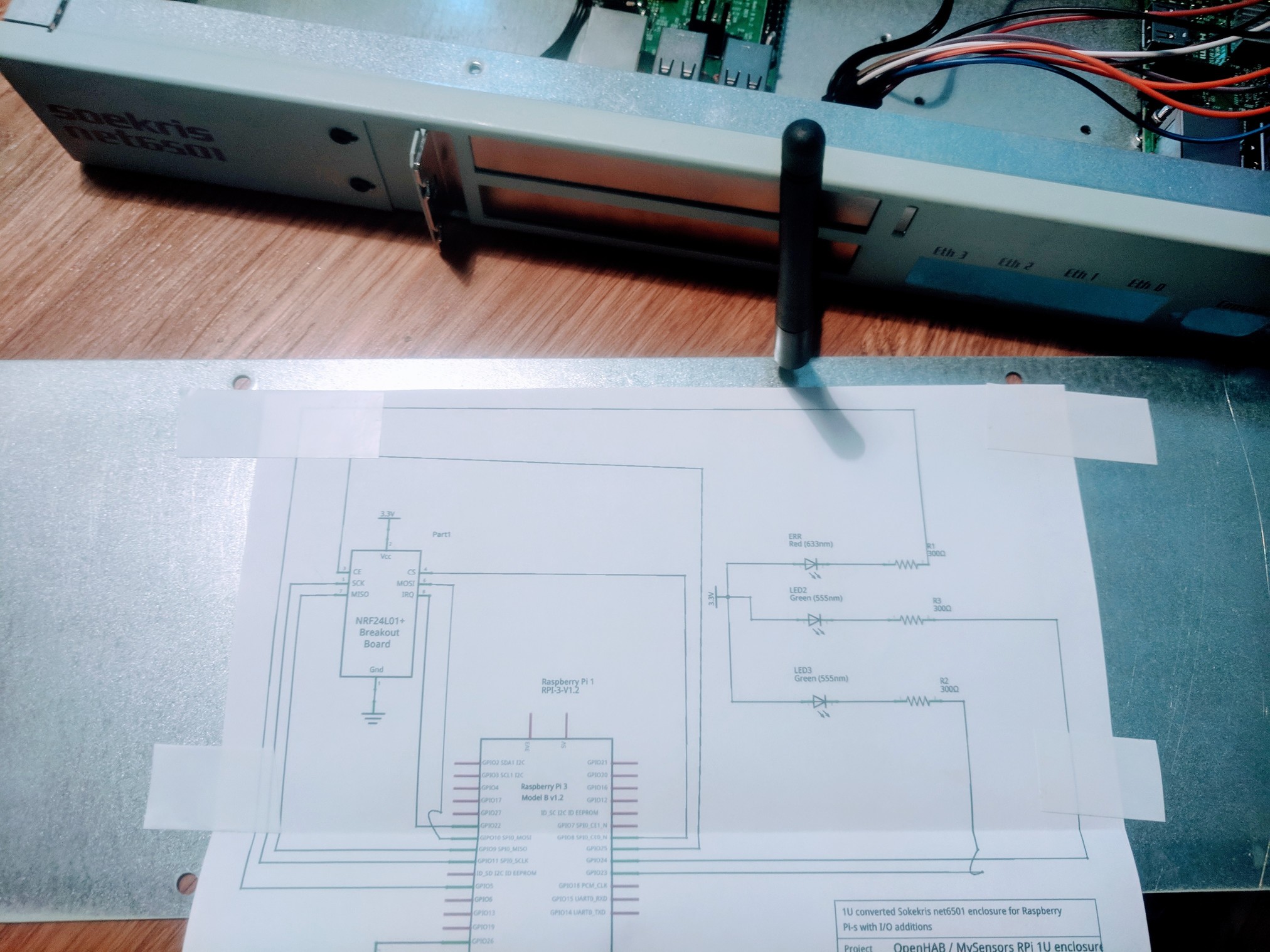
Documentation is important - in three months time, I won’t remember what connects to where. I created a quick diagram of the electronics in Fritzing and printed it onto the inside of the enclosure.

The resulting enclosure looked like this.
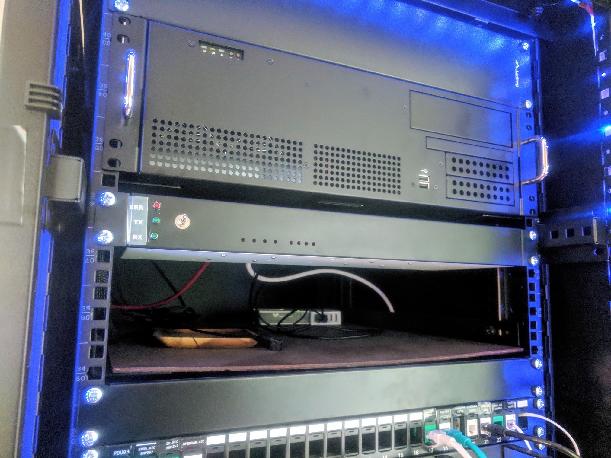
I installed the 1u enclosure to my homelab rack.
Results
Initial testing showed that everything worked OK - the long-range radio presented no problems and MySensors flashed the appropriate LED-s when radio activity occurred.
The back-end of the enclosure doesn’t look as good as it could - I fed the Ethernet and power cables directly into the PI-s, so it isn’t modular.
Future plans involve writing firmware to make the toggle switch work as well as populating the original Soekris 3mm LED sockets with LED-s: they will start showing service status on the OpenHAB (MySensors, OpenHAB, MySQL…).
Project Files
Project files are available from GitHub.