This is a story about how I pranked my colleagues by building a secondary remote for our wireless office doorbell and used it to perform the classical ding dong ditch prank.
I read about @SamyKamkar’s Digital Ding Dong Ditch in December 2014. He’s a cool hacker who made a tutorial about building a SMS-controlled Arduino remote for his friend’s wireless doorbell.
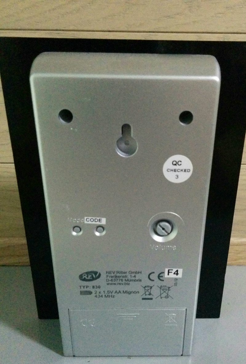
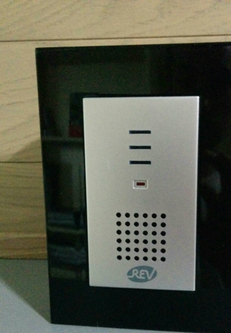
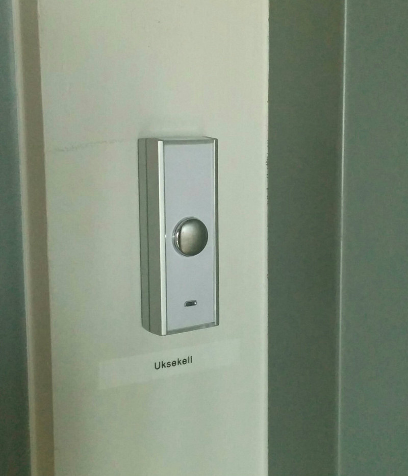
Half a year later our newly renovated office gets a wireless doorbell (REV 0046830). DING DONG!
The plan was to replicate Samy’s project in terms of the idea and implementation methodology. I would build a small remote for our doorbell and prank my tech-savvy colleagues by making them open the door only to find no-one there. Why? Because I can. But, seriously:
- elaborate pranks are fun
- I like electronics and creating things
- I like learning
The Plan
- Find the frequency of the doorbell
- Record the doorbell activation signal
- Build an Arduino prototype for playing back the signal
- Reverse engineer the signal from AM to HEX
- Build the production version of the module
- Build a software trigger
- Have some fun
Equipment Acquisition
For this project to work, I needed two pieces of equipment I did not already own:
- A 434MHz RF Link Transmitter for actually transmitting radio signals
- A SDR receiver dongle for recording radio signals from the real remote
The total cost for those was around 14€, cheap low-quality parts from China suited my needs well enough.
Find the frequency of the doorbell
Samy’s tutorial taught me the basics of how wireless doorbells operate: the button, once pressed, sends out a repeating radio signal. The doorbell “hears” this signal and activates. The signal has a specific frequency and pattern that my remote must match in order to activate the doorbell.
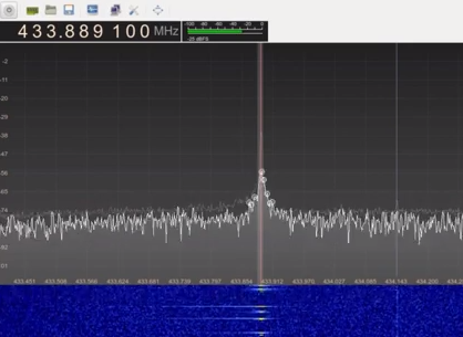
The frequency range of the doorbell was easy enough to identify.
- The frequency spectrum is regulated by EU and local laws, consumer electronics usually operate on one of the licence-free channels
- The doorbell actually specified the frequency on the back panel - 434MHz, which is in LPD433 UHF band, typically used in low-range remotes
Record the doorbell activation signal
How can we record radio signals?
Radio waves travel through the air all the time, even as you read this, they pass through your body. Man-made radio waves usually carry some sort of encoded information, like music or digital data. You’ll need a receiver to read those waves, the simplest of which is your regular FM radio.
FM radio operates at around ~88…108MHz. The doorbell I wanted to record is at 434MHz, so I needed to come up with something else.
Obviously, there are other devices for receiving radio signals. Unfortunately, they are either too expensive, difficult to operate or obtain.
Luckily, some clever hackers figured out a way of using cheap USB TV dongles - USB “sticks” that you can plug into your PC to turn it into a TV - in a non-standard way as a wide frequency range receivers: SDR-s (Software Defined Radios). There are various articles and talks on the web if you want to find out more about SDR.
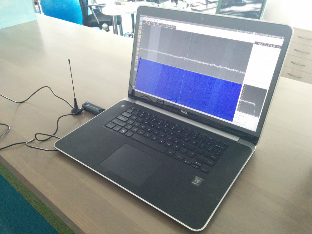
Capturing the signal
Once I knew the frequency, I could connect my SDR dongle to my laptop and run a program that allowed me to record any radio signals on that frequency. I came to work early, pressed “record”, rang the doorbell and captured some samples of a valid signal as a WAV file.
Build an Arduino prototype for playing back the signal
I had my signal recording, now I needed a way to play it back: a low-power AM transmitter operating at the 434MHz frequency. In addition, I would need a programmatic way of controlling the transmitter so I could specify the encoded information to send.
Solution: Arduino Uno + a cheap RF transmitter module.
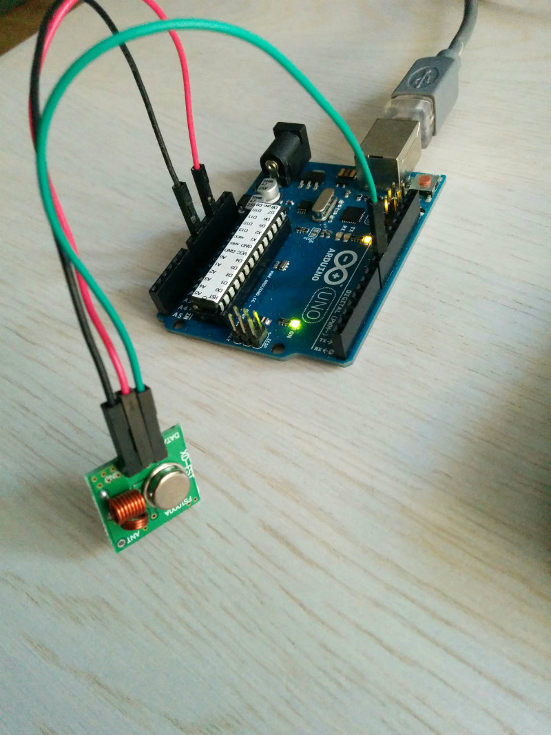
Connecting the module with the Arduino was easy enough: connect power, ground and the data pin and you’re done. I used Samy’s code as an example and adjusted it to fit my needs.
The result: I could specify the encoded signal I wanted to send in software and have Arduino actually send it over the air.
void singleRing()
{

  boolean previousLevel = false;

  for (int i = 0; i < SIGNAL_LENGTH - 1; i++)
  {

    if (previousLevel) {
      digitalWrite(TX_PIN, LOW);
    } else {
      digitalWrite(TX_PIN, HIGH);
    }

    previousLevel = !previousLevel;
    delayMicroseconds(triggerSignal[i]);
  }

  digitalWrite(TX_PIN, LOW);
}
Reverse engineer the signal from AM to HEX
I had a sample of the ‘correct’ signal that activated the doorbell and a way of sending arbitrary signals. The next step was to make my Arduino replicate the correct signal that would trigger the doorbell.
That took half a day. The process went like this:
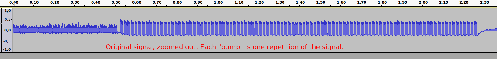
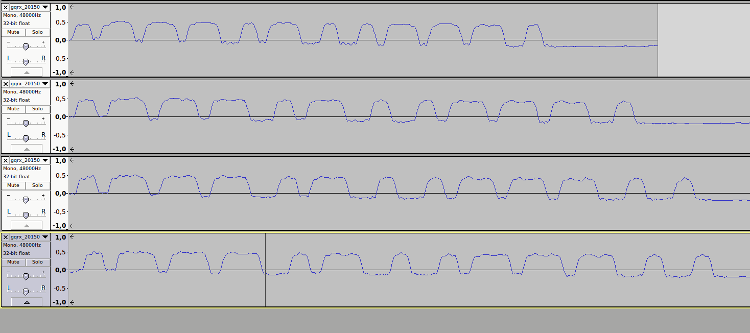
- Open the original signal in Audacity (it’s just a WAV file)
- Figure out the pattern - Samy explains how “high” and “low” levels translate to binary
Repeat:
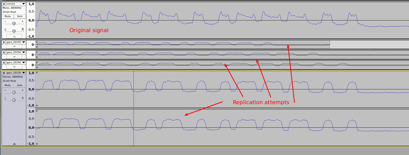
- Code the pattern into Arduino
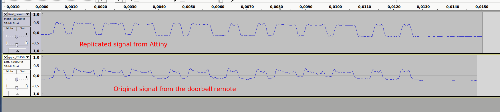
- Play the signal with the Arduino, record the result
- Compare the result against the original
- Adjust timing offsets and delays of the replicated signal until it matches the original
The signal for doorbell activation was
SHORT_UP, SHORT_DOWN, LONG_UP, SHORT_DOWN, LONG_UP, SHORT_DOWN, LONG_UP, LONG_DOWN, SHORT_UP, SHORT_DOWN, LONG_UP, LONG_DOWN, SHORT_UP, LONG_DOWN, SHORT_UP, SHORT_DOWN, LONG_UP, SHORT_DOWN, LONG_UP, SHORT_DOWN, LONG_UP, LONG_DOWN, SHORT_UP, LONG_DOWN, SHORT_UP, LONG_DOWN, SHORT_UP
This is 0111010011100 when translated into binary and 0E9C in HEX notation.
Once I was reasonably certain I had successfully replicated the original signal, I took the Arduino prototype to the office for a test drive - outside working hours, of course. I powered up the Arduino and the doorbell rang.
Sweet success! Up until now, I wasn’t sure my plan would even work, it was good to get a proof-of-concept verification.
Build the production version of the module
I could have ended the project right there as I had - if somewhat bulky - way of activating the doorbell. However, I wanted to make this portable and build a standalone version.
The plan: Use an ATtiny85 microcontroller to build a battery-powered version of the remote.
Requirements
- Runs on a single 3V CR2032 battery
- Uses as little power as possible
- Is physically as small as possible
- Is re-programmable
- Has a manual trigger (button)
- Has header pins for using an external trigger (Raspberry Pi)
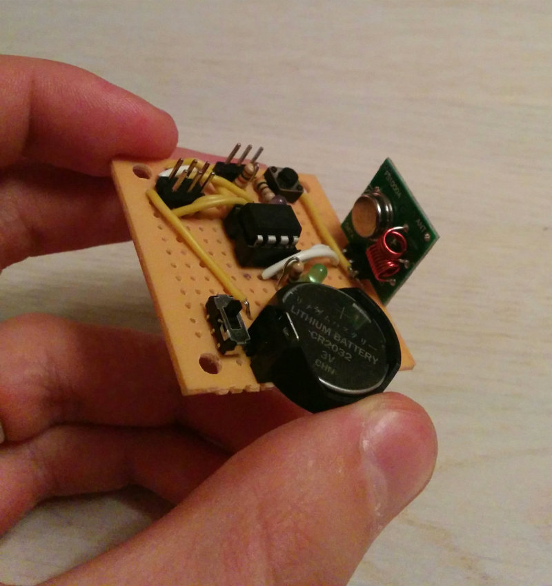
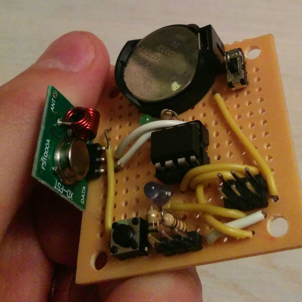
The build
Building the module from scratch was done over the weekend. I started by drawing up the circuit I wanted to build in Fritzing.
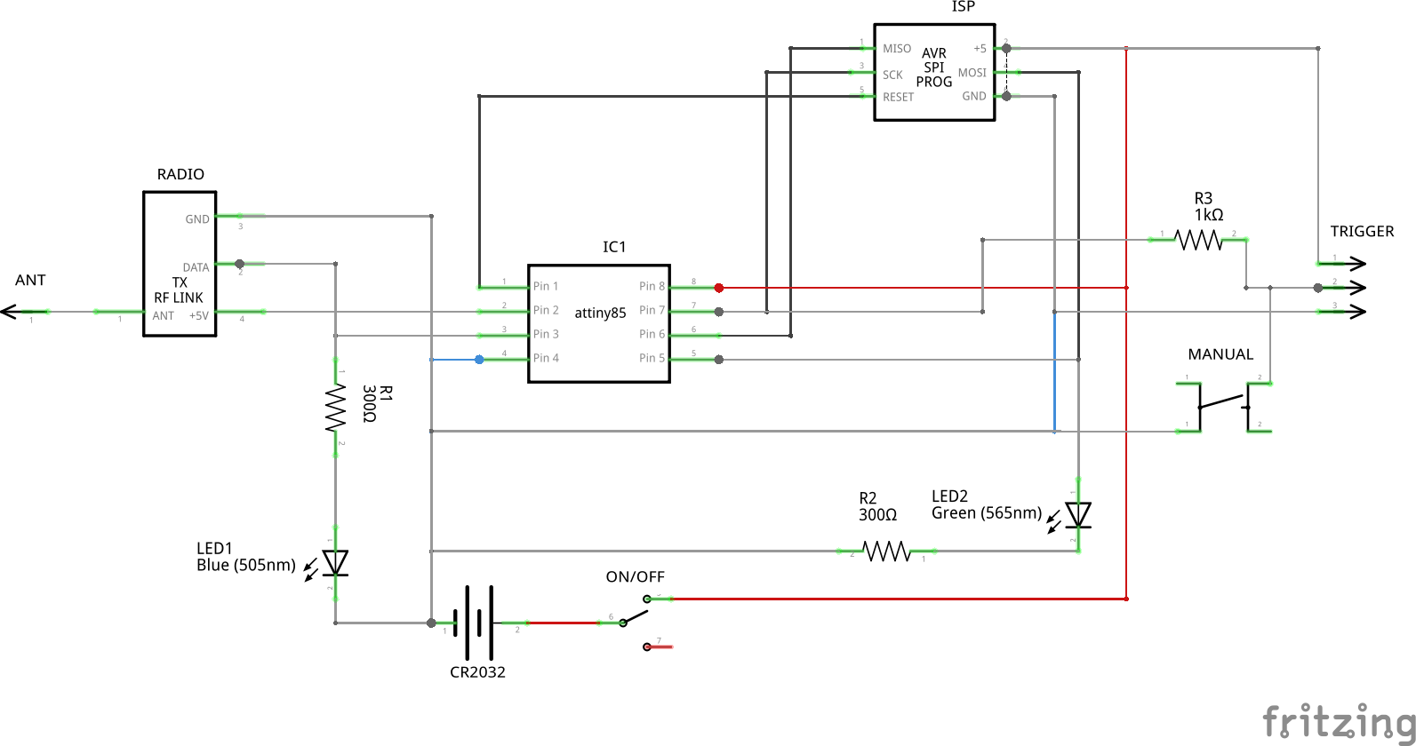
The circuit is quite minimal, but with some added bazang:
- ON / OFF switch
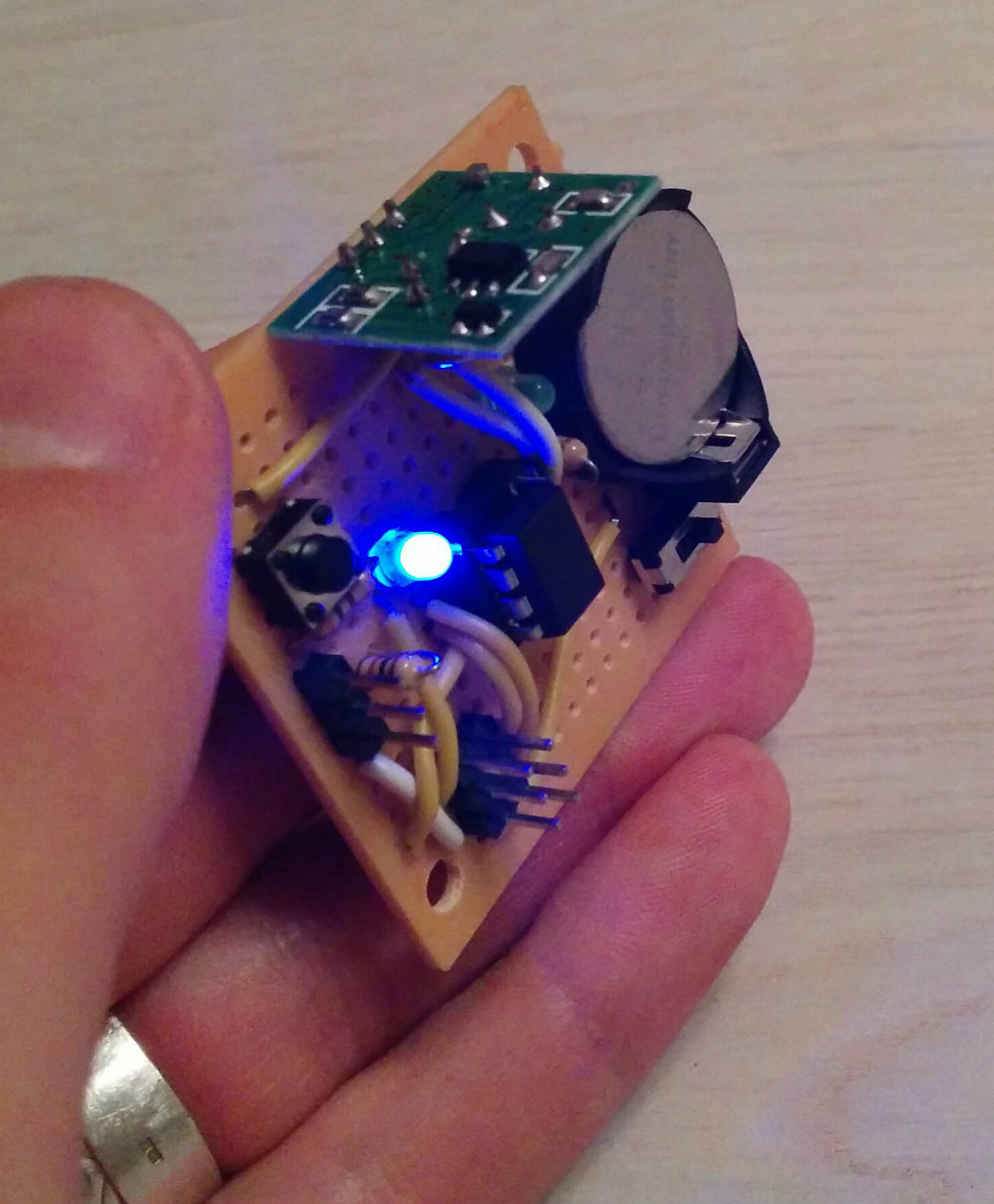
- A LED for indicating that the transmitter is currently active
- A programmatically controllable LED for blinking every 5 seconds as “power on” indicator
- A button for activating the device
- Header pins (PWR / GND / TRIG) for external activation
- ISP header for reprogramming
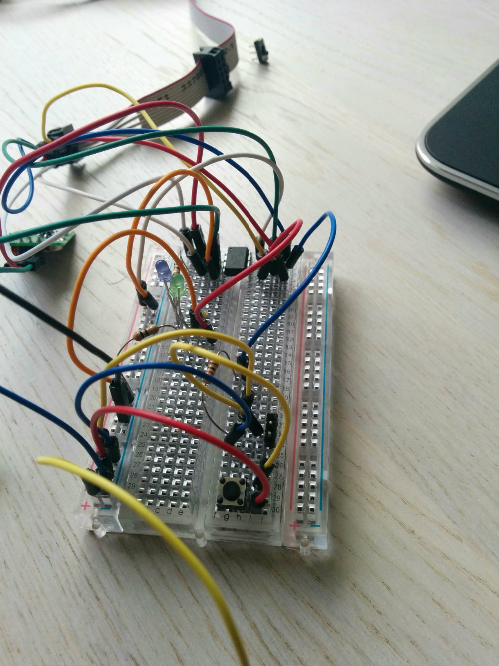
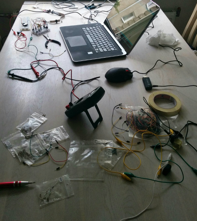
Next, prototyping on a breadboard. I got Attiny85 to run on a clock speed of 8MHz, to read the trigger pin and to send the correct signal when activated.
When I was certain the prototype worked, I took a spare piece of solder-able breadboard and soldered the components onto it. Everything fit very neatly and looked quite good.
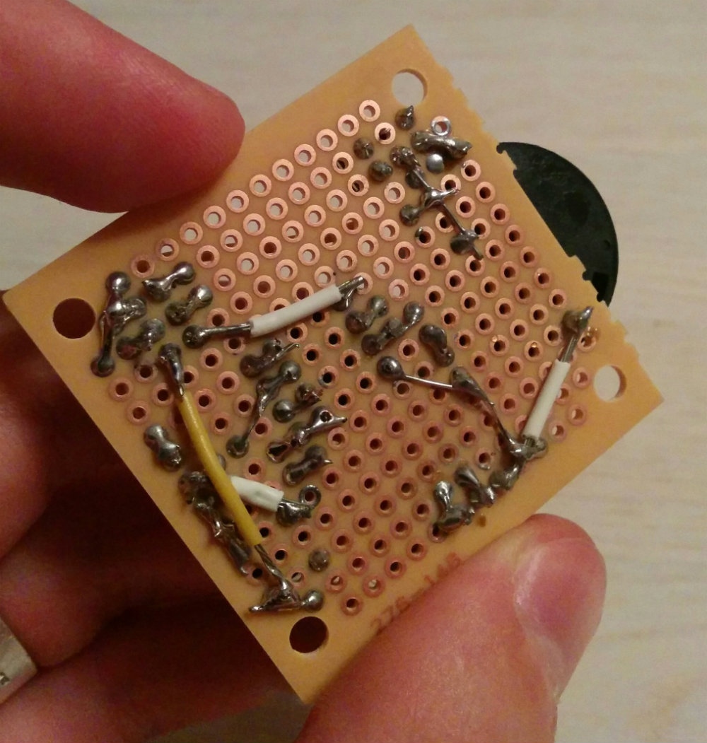
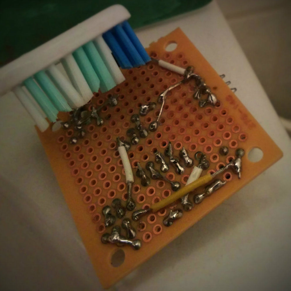
I tested the connections during and after soldering for shorts and discovered a major fault: the resistance between various IC pins (ATtiny85 I/O pins) was ~20kΩ! This would mean that the board was unusable because of shortages between various signal lines.
I could discover no solder bridges or shorts so I concluded the problem was in the solder flux I had used liberally during assembly. I took a toothbrush and some rubbing alcohol and gave the module a cleaning bath in the sink. After drying, the problem was solved.
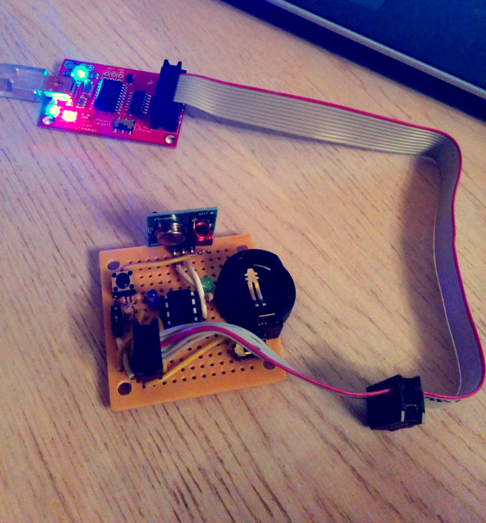
Build a software trigger
I had my pocket-sized doorbell remote that could ring the office doorbell either with a physical press of a button on the module or by external activation (another device activates the active-low input pin on the module).
I wanted to make this even more awesome and activate it remotely via an IM message. My company uses software called Fleep - a competitor to Slack - for in-house communications. I had also set up an instance of Hubot, a chat bot from GitHub. The idea was to make the doorbell ring by telling Hubot (Moonica) to ring the doorbell.
This was simple enough to implement. Hubot was already integrated with Fleep (I had written an adapter), all I needed was for Hubot to pull the trigger pin of the module to LOW when he got the command.
I set up a Raspberry Pi and wrote a simple HTTP web hook on it. The Pi was attached to the module and hooked into LAN, accessible by our in-house Hubot instance. The result: I could send a HTTP POST request to the Pi and it would activate the module, which would send a radio signal to the doorbell.
I wrote a small Hubot script that would POST to this HTTP endpoint whenever Hubot heard the command ding-dong in any of the chats.
Have some fun
I used my evil creation once or twice a day for four days, undetected. I would send a Fleep message to Hubot, the doorbell would ring, someone went to open the door and there was no-one there. People were confused and started to expect being pranked.
Some comments from the people who went to open the door:
- “I bet there’s another doorbell on the next floor and then the radio waves like…”
- “Who’s doing this?”
- “How is this possible?”
Finally (I’m not Dr. Horrible to keep this up for weeks), I told a colleague about this and he told Hubot to ring the doorbell in the floor chatroom, for everyone to see what’s happening.
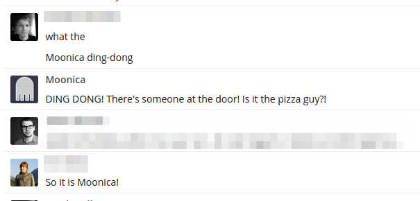
- “So it is Moonica [Hubot]!”
- “Enough of this nonsense, you people aren’t the ones who normally open the door”
- “So this month’ fun prize goes to Ando - I guess :)”
- ”((Y)) impressive prank and implementation, nerdy stuff”

Muahahaaa!
References
All the project files - hardware schematics, firmware, Hubot script and HTTP POST hook - are published on GitHub. @samykamkar, thank you for the original idea and a tutorial, this wouldn’t have happened without your input.
Update: two years after this, I built a IoT smart doorbell.