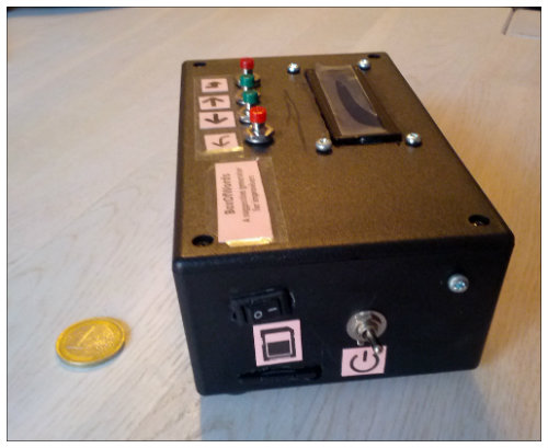
BoxOfWords is a hand-held, cigarette-box sized electronics project for improvisational theatre practitioners.
The purpose of the project is to offer randomized word suggestions during an improv workshop or a training session.
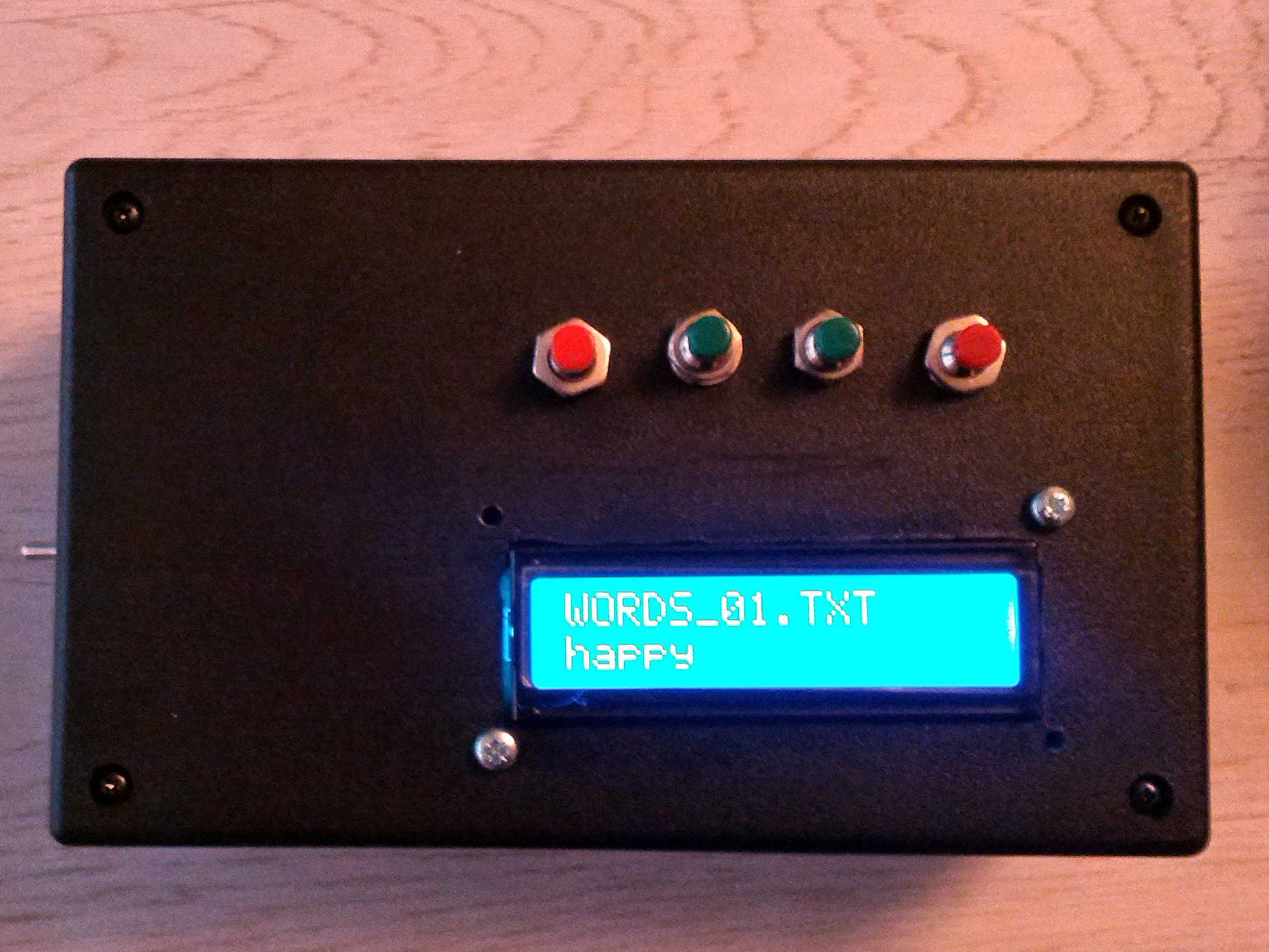
BoxOfWords has a memory card reader, control buttons and a small LCD screen. The improviser selects his preferred word file (emotions, locations, professions…) and can call up new randomized suggestions to the LCD screen with a press of a button.
The project was built as a present to Trent Pancy, the organizer of the Third Annual Finland International Improv Festival.
This was my second successfully completed production electronics project and the first to include a custom-made PCB and run on batteries.
Operation
The purpose of the device is to offer randomized words of a certain word category file. For example, we have the following text files (on the SD card): emotions.txt, locations.txt, adjectives.txt and so on. The user selects his desired category (word file) and the device calls up random words from that file.
There are four navigation buttons: back, left, right, enter.
A simple usage scenario would be as follows:
- Power On
- Main Menu is shown (the title of the first file)
- The user navigates to the desired file ([right], [right], [enter])
- A random word from that file is shown
- The user wants another random word ([right])
- The user wants another category ([back], [right], [enter])
- A random word from that file is shown
- .....
- Power Off
Technical Challenges
I learned a lot through the project. Here are the things I found most challenging.
Power
Portable projects need a power source. I decided to use 4xAA batteries. They’re cheap (compared to Li-ion or power banks), offer larger capacity than a 9V battery and output just the right voltage (6V). An article on Let’s Make Robots taught me how to regulate that voltage to a stable 5.0 volts using the Lm2940ct-5 low-dropout voltage regulator. I soldered my first power regulation circuitry.
Reading files from an SD card
The main menu should let users choose between txt word files on the SD card. Initially, I planned to just read the contents of a directory and list all the found files on the LCD. After over six hours of hacking with the SD library I was unable to get a file listing into a workable array of strings so I abandoned the idea and decided to use preset file names: WORDS_00.TXT, WORDS_01.TXT and so forth.
This put some limits to the project and I settled on having exactly eight files to choose from (this is an artificial limit, I could as well have chosen to have sixteen). That way, I would know exactly which files are present on the card.
The user still needed some way of distinguishing between files (which file contained Emotions?) so I created a settings system.
The SD card has a file called SETTINGS.TXT which looks like this.
brightness=199
scrollSpeed=180
title0=Emotions
title1=Professions
title2=Relationships
title3=Locations
title4=Random words
title5=Adjectives
title6=Film Styles
title7=Activities
The file contains two runtime settings and human-readable titles for all of the eight word files. The titles are mapped to the files (title0 = WORDS_00.TXT) and the LCD shows not the actual file name but the configured title.
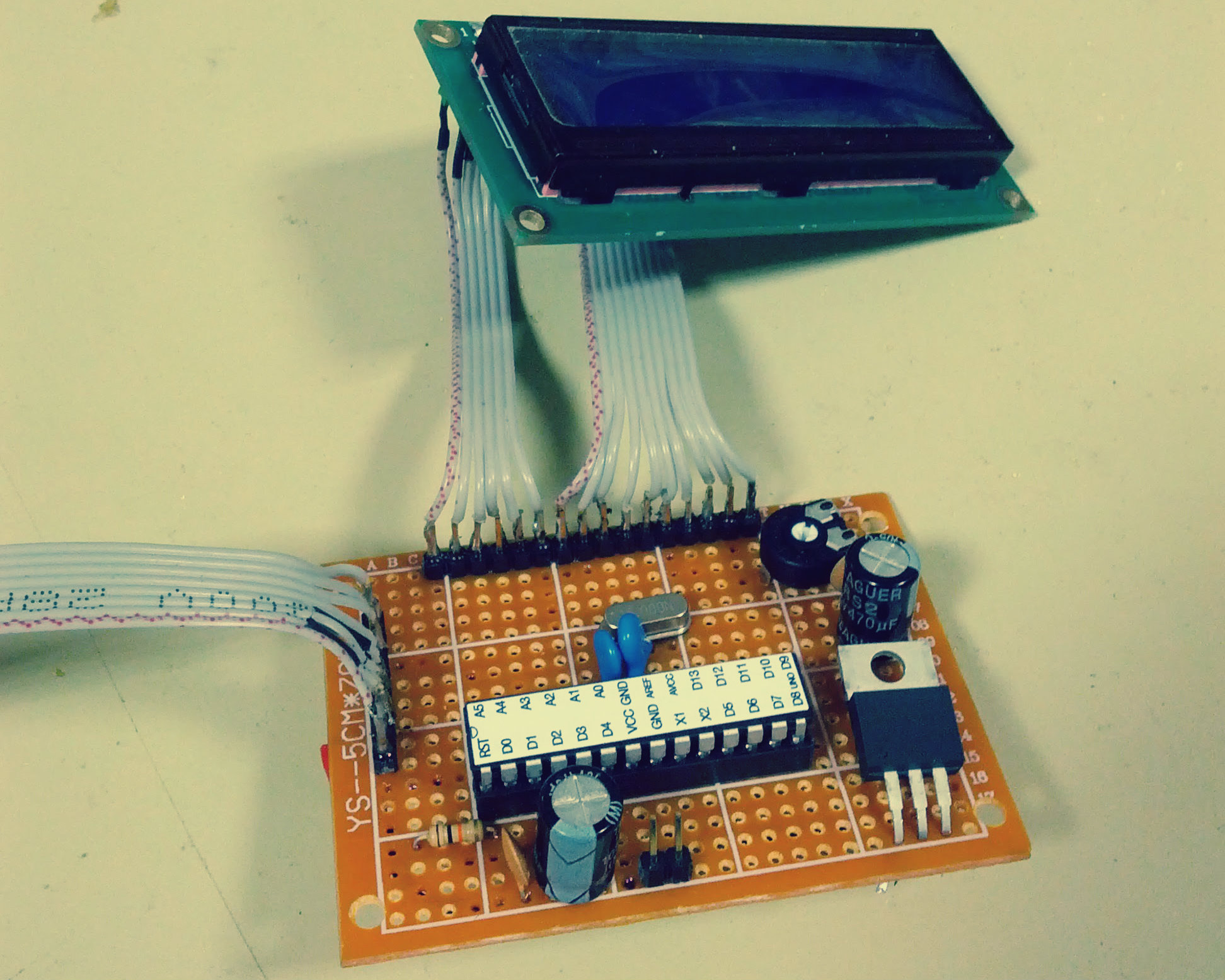
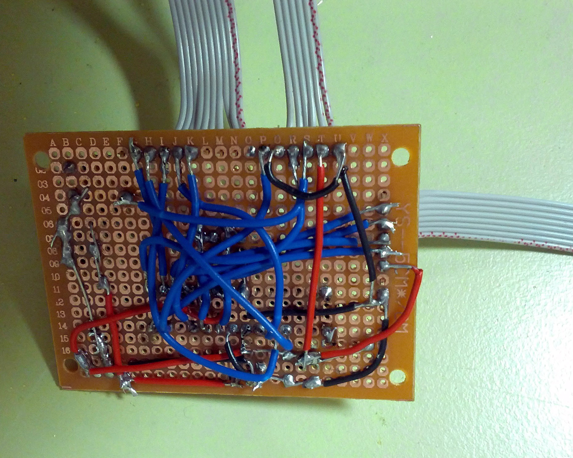
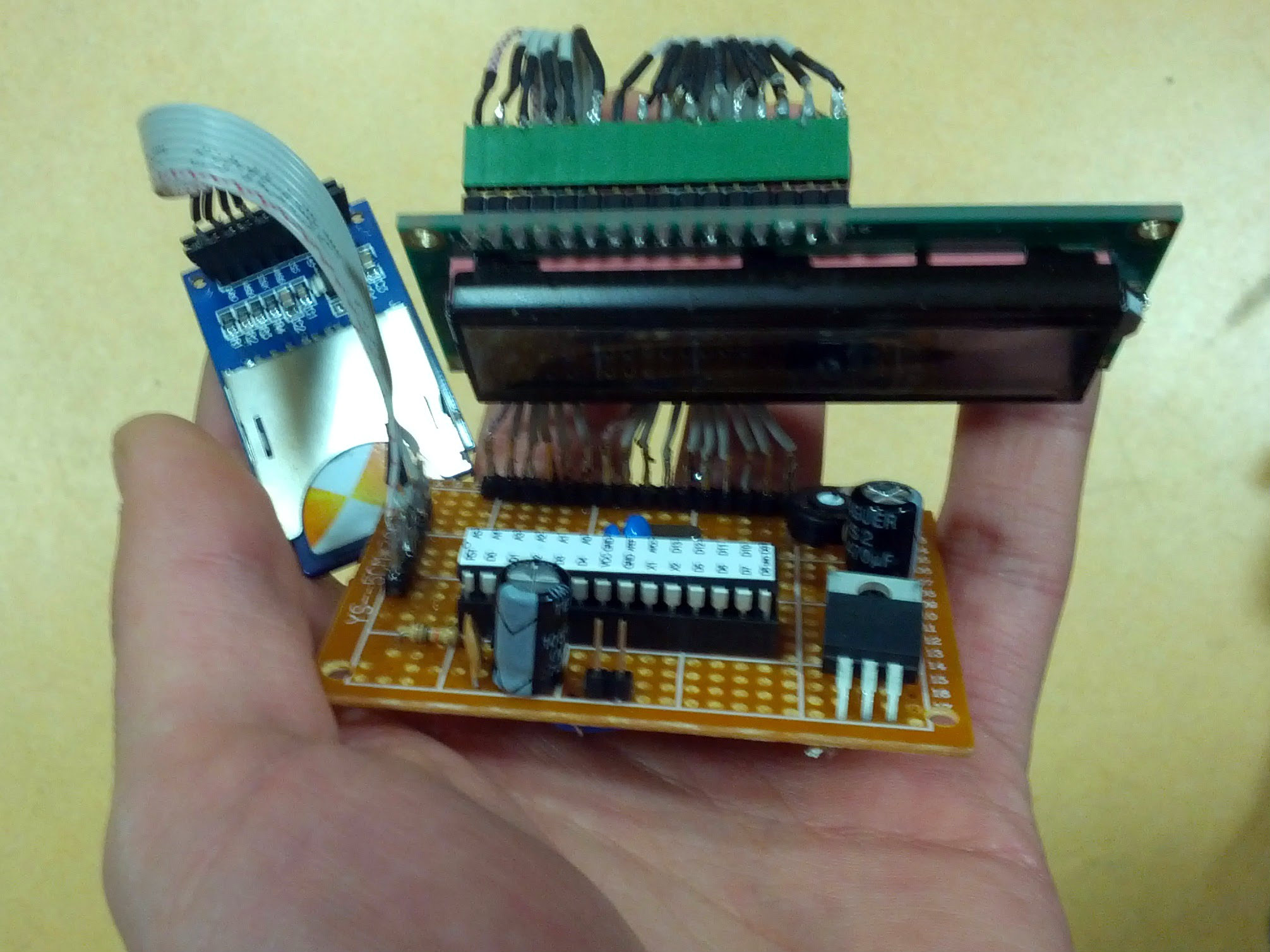
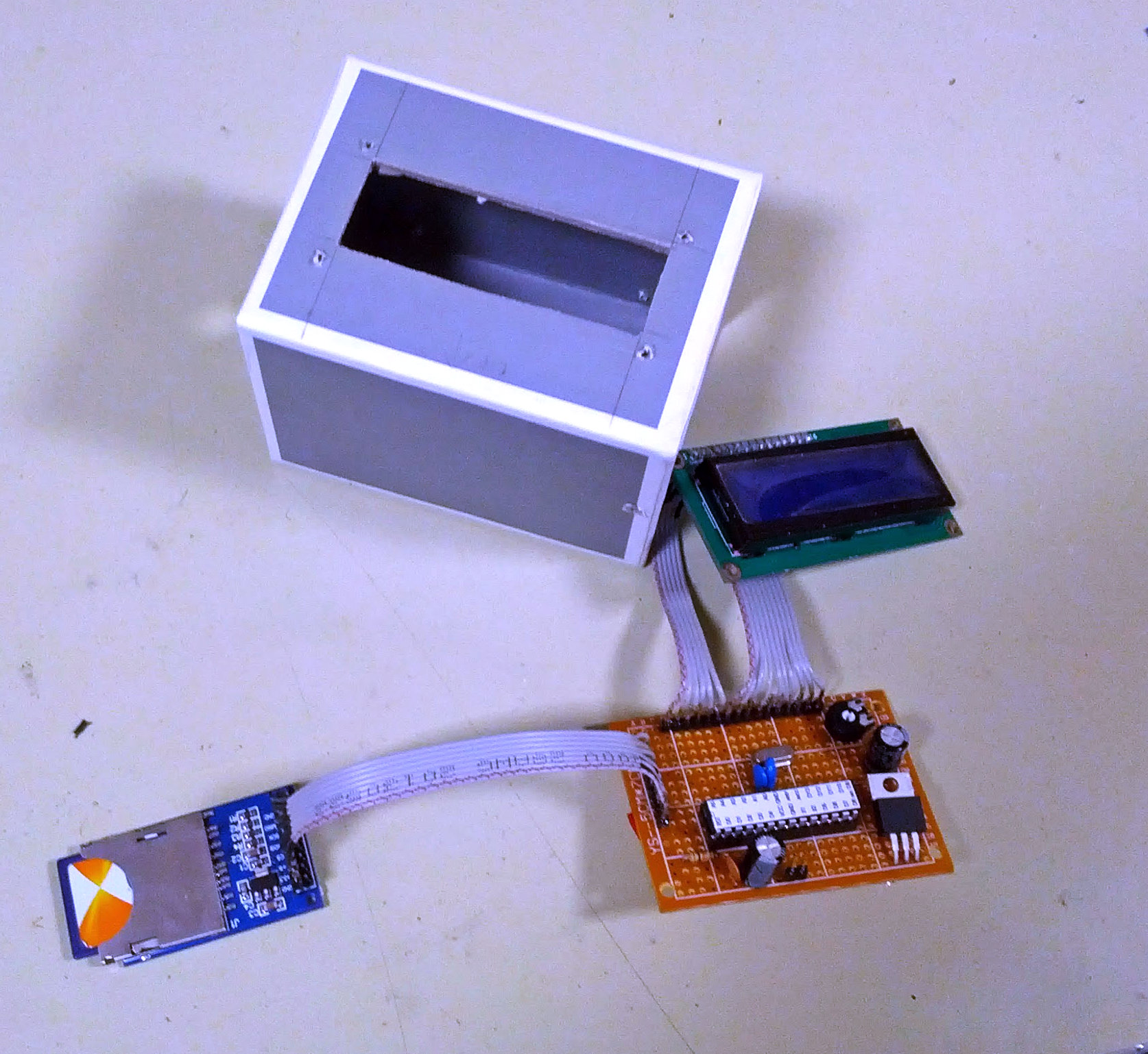
The PCB
Soldering the PCB was a challenge on its own. I’ve tried to make a PCB before, failed twice, succeeded once. The task involves working with delicate parts, lots of small wires and tin. There’s always a chance for something shorting.
I spent a whole day with preparing the wires (instead of soldering ribbon cable directly to the board I opted for a more modular, but complex solution and used headers) and soldering the parts together. At the end of the day, I was spent but victorious: all of the connections worked, there were no shorts and I had my spiders-nest of a PCB, ready for action.
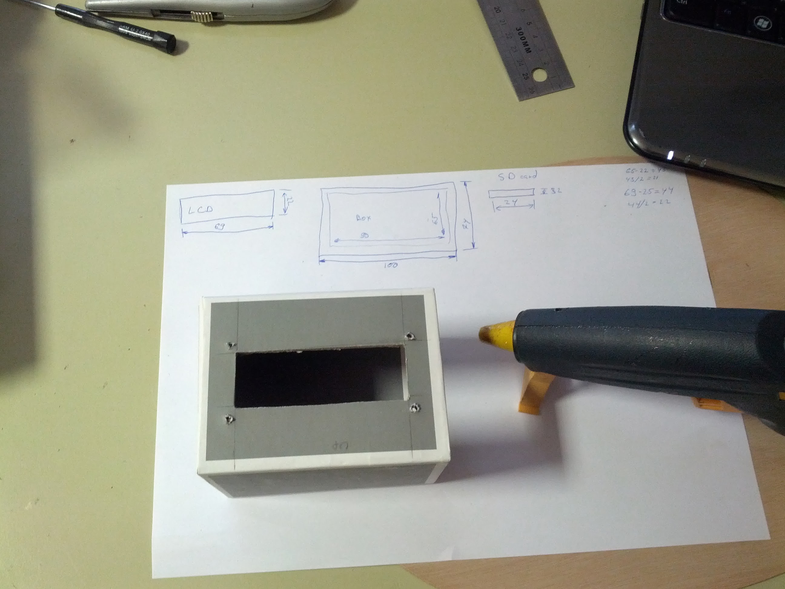
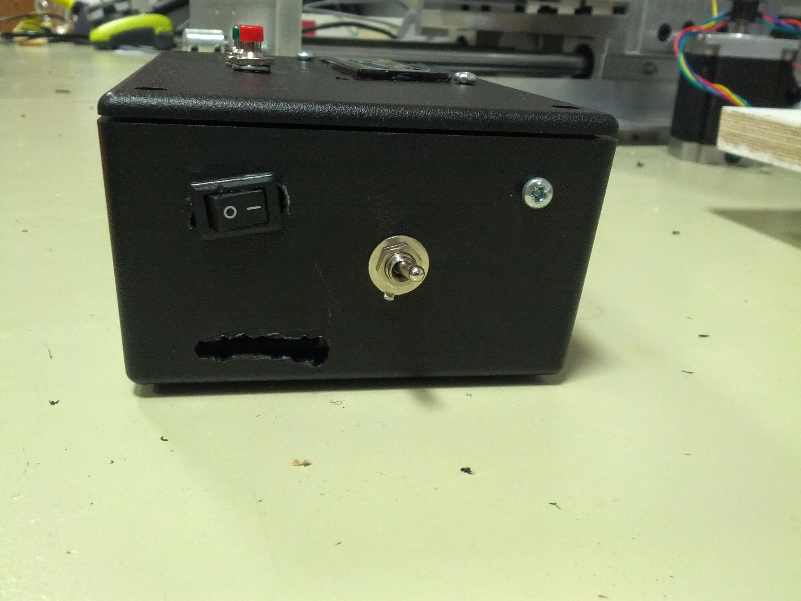
Physical enclosure
The project needed a nice-looking, sturdy case which would ideally be as small as possible for comfortable handling. The material of the enclosure needed to be easily workable with hand-held tools for I have no access to 3D printing or computerized mills.
The first attempt of creating the enclosure was with a thick paper pencil holder I saw at the supermarket. The material was easy to work with (it’s basically paper) and sturdy enough to protect the project from deformation. In the end, the enclosure proved to be too small to fit all of the components and wires and I had to look for an alternative.
The local electronics supply store stocked the perfect plastic box with thick walls, the right size and sleek look. It took some work and creative use of tools to create the openings for the LCD, SD and switches, but the result was satisfactory.
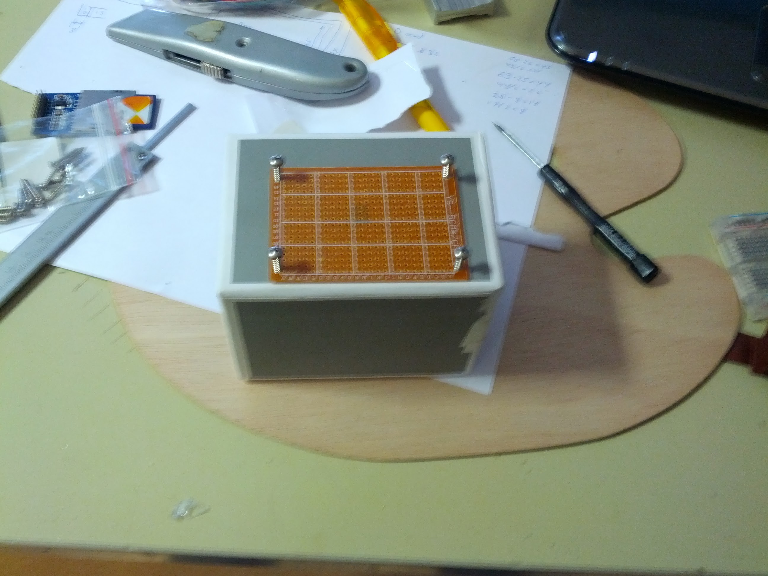
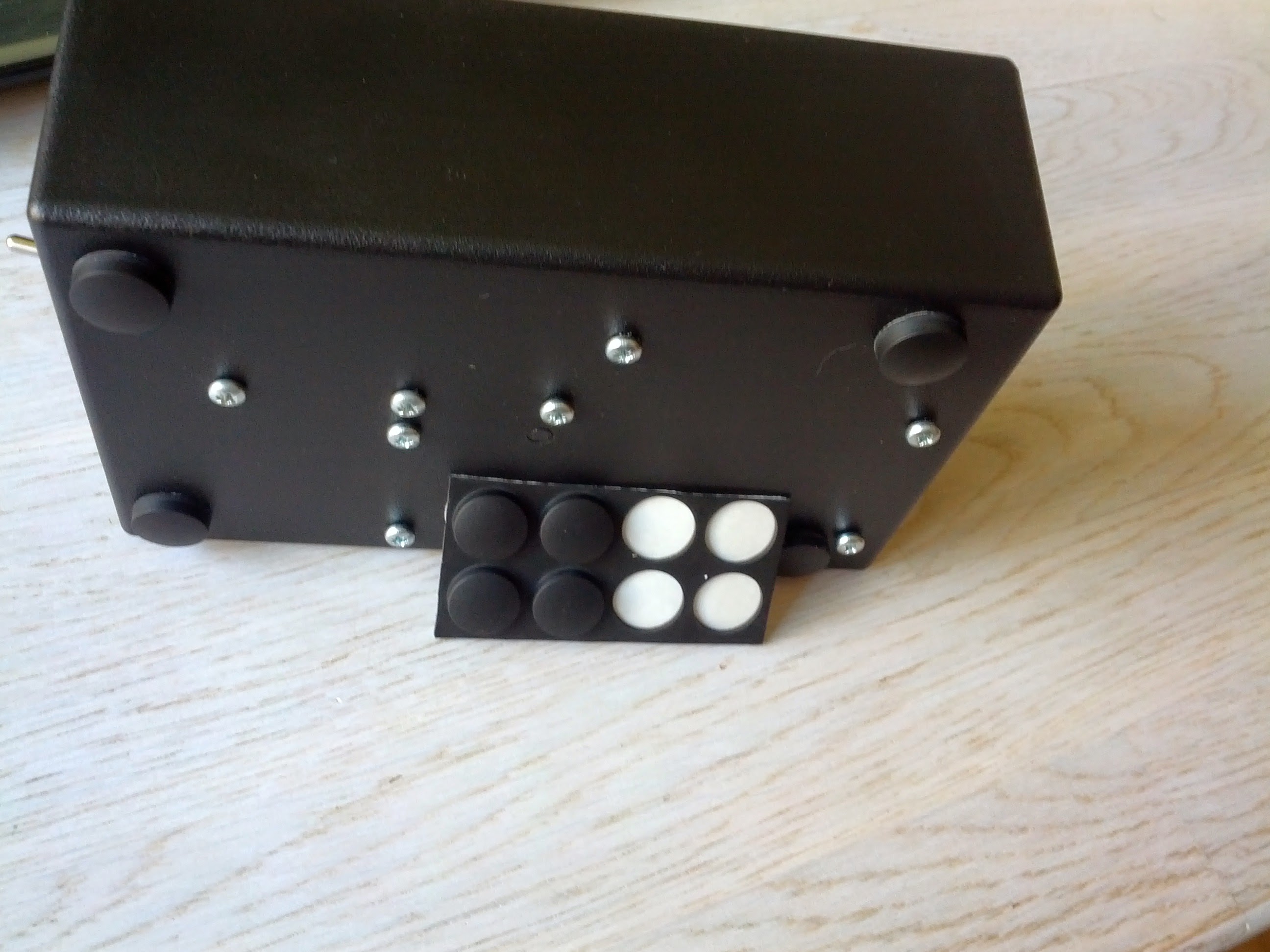
Fixing the parts in place
The various modules needed to stay securely in place inside the enclosure. For that, I used screws, super glue and velcro.
The project gave me reason to visit the hardware store for the first time in my life, voluntarily. I bought a few dozens of 3mm metal and wood screws (the smallest they had), which fit perfectly to the PCB and LCD mounting holes. The SD card required smaller screws which I was unable to obtain so I used super glue which turned out to be really effective.
Inspired, I thought to glue the power switch to the enclosure - but it turns out it’s easy to superglue a plastic rocker switch shut. I had to install a replacement.
A lot of 3mm screws, bolts, nuts and washers were used to secure various elements. I used a combination of screws and velcro to secure the battery pack.
Long text on the 16char LCD
I had to take into account that some of the suggestions might be long: Acting Director / Stage worker, longer than the maximum length of the LCD. The solution? Scrolling the text (marquee). Programming the function for that caused some headache, the end result was satisfactory, but could have been better.
Reading push-buttons
I’d made a mistake in soldering the four input buttons: pressing one button would result in the neighbouring buttons analogRead value to lower dangerously low, too. As a result, pressing one button would be identified as pressing two buttons at once. I had a choice: redo the button module (some hours of risky PCB work) or create a software workaround.
I opted for the latter and created a function that determined which of the buttons had the closest analogRead value to ground. Still, a logic error in the code that dealt with reading the buttons delayed project completion by a week, resulting in missing the perfect window for handing over the gift.
I discovered the error some time later during a debugging session and was quite annoyed at myself when changing
if (buttonValues[i] < buttonValues[i-1])
to
if (buttonValues[i] < buttonValues[lowestIndex])
yielded the desired result.
Lessons learned
I’d do a few things differently if I had to start over.
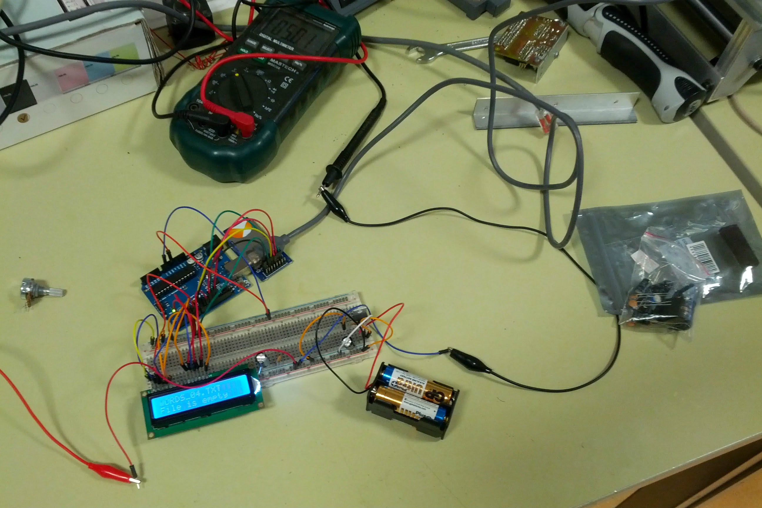
Include a programming header
I had a breadboard setup of my project attached to an Arduino where I tested the code I developed. Once I was reasonably certain the code worked as I wanted it to I would remove the Atmega chip from the PCB, put it into the Arduino, program it, then press it back into the PCB IC socket. The process was time consuming, delicate (at any point I could have damaged one of the pins of the IC) and annoying. My next Atmega PCB will include a convenient ICSP header that allows me to program the chip without removing it from the socket.
Cannot set LCD contrast with PWM
At first, I wanted both the brightness and contrast of the LCD to be controllable from the software. I used two PWM pins for that. Unfortunately, the contrast can not be controlled as simply: the LCD module went nuts and started displaying gibberish.
After some searching around in the Arduino forums, I found an explanation: you need a low-pass filter for that. I didn’t bother and just used a small trimpot.
Test for power consumption
I didn’t test the power usage of the project before it was assembled and already shipped. Getting an idea on how much power the project consumes, both on standby and operating mode (reading the SD card) would let me give an estimate on how long the batteries last.
Optimize power
There wasn’t a lot of focus on power optimization. I know I could increase the battery lifetime by a large margin if I tried: shutting of the IC when no buttons are pressed, caching SD card results, dimming the backlight…
Think about PCB fabrication
Frizing, the software I used to design the circuitry, also has a PCB fabrication service. Basically, I send them the blueprints for the board and get a professional, sleek-looking PCB some days later in the mail, ready for soldering.
This would look so much more professional and as an added bonus - no jumper wires. A nest of crossing wires beneath the board is a risk: any one of them might come loose, especially during mounting.
I calculated the fabrication of my board to cost around 30-40 euros.
Put more work into designing the exterior
Some of the edges of the holes I cut into the enclosure aren’t smooth. Putting more effort into that would yield more professional-looking results.
I used ordinary paper to print out the labels for the controls, then laminated the printout. Using a photo paper would look nicer or better yet, figuring out how to paint the designs to the plastic…
Skill-ups
Skills obtained or perfected with this project: (Arduino) / C programming, PCB design and production, manufacturing (enclosure), electrical engineering, soldering, UX design
Conclusion
Overall, I am very satisfied with the result. I stared the project during the winter of 2014 while still in the army (I had my minimal prototyping electronics kit and a laptop with me, I used to work on the programming during our scarce spare time in the common area) and finished in June. The day when the last bug (malfunctioning [enter] button) was fixed and I finally mailed the finished project to Trent felt so fulfilling - I had accomplished something that took me a lot of time and effort to create.
I’m satisfied with the amount of knowledge I got from this project. The code and schematics are open source, hopefully it’s of help or inspiration to someone somewhere.